April 2004
![]()
AutomatedBuildings.com
[an error occurred while processing this directive]
(Click Message to Learn More)
April 2004 |
[an error occurred while processing this directive] |
|
|
Christer Johansson,
M.Sc, Submitted by |
Is there a conflict between mixing valves and pumps with variable flow? How do you connect a boiler circuit with a heating circuit? Do you prefer a 4-way mixing valve or injection pumping? This article is intended to give some answers. First, what is your goal?
|
[an error occurred while processing this directive] |
Probably, you are primarily interested in good performance i.e. smooth control and protection against too high or too low water temperatures. Let's first take a closer look at a traditional 4-way mixing valve and then compare it with a pump with variable speed.
The components valve and pump - what's their performance?
Valve
The max capacity of a valve when fully opened is determined by its Kvs
[m³/h] or Cvs [gpm] value which specifies the water flow through the valve at a
normalized pressure difference [ΔP0] and a normalized density
[ρ0].

 (Eq. 1-2)
The water flow through the valve varies with its opening rate and depends on the characteristics for the actual valve. The characteristics of a valve might be visualized in a diagram showing % valve opening vs. Kv, see fig 1. Often four way valves have a "linear" characteristic but some are also more progressive i.e. "Equal Percentage".
 Fig
1. Example of flow characteristics of a valve
Rangeability will normally be something between 20 and 100 when the pressure differential is constant. When the valve is placed in a circuit with other pressure reducing components, only a part of the total pressure in the system will be available to the valve.
![]() (Eq. 3)
(Eq. 3)
When the valve is placed in series with a pump running at constant speed, the pressure differential over the valve will increase when the heat load is decreasing and the valve is closing.
Pump
When you select a pump, you will look for sufficient capacity at maximum load.
Normally the data for a pump with fixed speed are presented in a diagram as the
characteristics curve, see fig 2. The curve for [100 % speed] shows pressure
head vs. water flow. In most systems or circuits the pump has to interact with
other active components such as control valves and thermostatic radiator valves.
If you put the characteristics curve of a heating system into the same diagram
it might look like the curve [dP,HS] in fig 2. The curve [dP,HS] is the sum of
the pressure drop in the fully open control valve [dP,valve] and the pressure
drop in stationary equipment [dP,stat]. The curves for the pump and for the
heating system cross at the working point A.
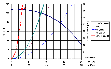
Fig 2. Characteristics of pump with fixed speed
When the heat load is low, the valve will reduce the flow and the system curve will move. The curve [dP,HS mod1] represents a situation where the valve has closed approximately to 1/3 of it's max opening and the water flow has decreased to 3 m³/h. The new system curve crosses with the pump curve at the new working point B. The pressure over the system will increase if pump speed is unchanged.
For a pump with variable speed the data are presented in a diagram with different characteristics curves for different speeds, see fig 3.
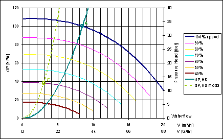
Fig 3. Characteristics of pump with variable speed
[an error occurred while processing this directive]For commonly used pumps the speed can approximately be regulated down to 40 % of the nominal speed. At lower speed the pump will have a low efficiency and there might be heat problems. Following are the relations between a change in speed [n] to change in flow [Q], pressure [H] and power [P] respectively.
![]() (Eq. 4-6)
(Eq. 4-6)
When the heat load is low, the valve will reduce the flow and the system curve will move, but at the same time the speed of the pump may be reduced. A reduction of the speed of the pump will give a new characteristics curve for the pump. The pressure differential over the valve will at the same time decrease. You will get a new characteristics curve for the system, see fig.3. The curve [dP,HS mod2] represents a situation where the valve has closed approximately to 1/2 of its maximum opening and the water flow has decreased to 3 m³/h. For the new working point C the pump speed is reduced to 60 %.
In a circuit without active components, where the pressure differential over the system only depends on friction losses in pipes and other passive components the actual working conditions will steadily follow one single curve like [dP,HS]. Water flow will then be directly proportional to the speed of the pump. Rangeability will be 2.5.
When speed of the pump is decreasing it will rapidly reduce consumption of power. The minimum need for water flow or pump speed varies over a year proportional to the outdoor temperature. In figure 4 is shown how many days of a year a certain level of speed is required and also the corresponding power consumption.
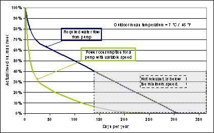
Fig 4. The minimum need of water flow to the heating system for different days of the year and the corresponding power consumption if a pump with variable speed is used
Conclusion 1
In most cases there is no conflict between using valves and using a pump with
variable speed. On the contrary they will benefit from each other.
Variable speed drastically reduces power consumption of the pump.
With constant pump speed it will be more difficult for the mixing valve to control properly.
If there are no valves in the system the pump will have little ability to regulate the flow.
The mixing circuit between the boiler and the heating system
Let's look at two typical ways to create a mixing circuit by using an ESBE 4-way mixing valve and by using a pump with variable speed, see fig 5-6.
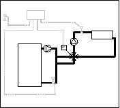
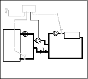
Fig 5. Mixing by motorized 4-way valve Fig 6. Mixing by pump with variable speed.
The main advantage of the shortcut in the boiler circuit is that flow through the boiler won't be affected by changes in the radiator circuit. You will always get sufficient flow through the boiler. And if the controller is sophisticated enough, you can get full boiler protection. Also the radiator circuit can be protected against too high temperatures.
 ESBE 4-way mixing
valve
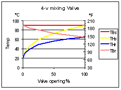
The valve will have high authority when placed in the mixing circuit. When it is
fully opened all water to the heating circuit will be taken from the boiler
loop. A valve with linear characteristics will give temperatures as in the chart
in fig 7.
If the temperature in the heating circuit has to be limited to 60 °C (140 °F) the valve will never open more than approx 30 %.
The performance of the valve might be increased by different means. One possibility is to use a bypass as in fig 8-9. With the mixing valve in the by pass circuit the flow through the 4-way mixing valve can be adjusted to achieve the right temperature at maximum load.
Fig 7. Temperatures when using a linear 4-way valve
|
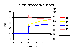
Explanation to figures 7 - 10: TBs = Supply temp
from boiler to mixing
circuit THs =
Supply temp to heating circuit |
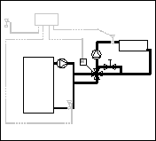
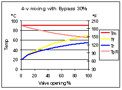
Fig 8. Bypass circuit Fig 9. Temperatures with bypass circuit
Notice that there is no extra pump in the mixing circuits in fig 5 and 8. The flow of water is induced by the pump located in the heating circuit on the other side of the 4-way valve. Care must be taken to avoid pressure differences in the mixing loop caused by friction losses and the valve must be placed close to the boiler loop. If there are pressure differences to overcome, the mixing circuit won't work. The heating circuit will then get warm water only when the valve is close to its fully opened position.
 Pump with variable
speed
When the pump is running it will inject hot water from the boiler circuit into
the radiator circuit, see figure 6.
By changing the speed it will be possible to control the flow of water from 40% to 100%. That will give temperatures as in the chart in fig 10. When heat load is low the pump will have to work under on/off conditions. That will be the case about 50 % of the heating season regarding to figure 4.
To optimize the performance of the mixing circuit it has to be permanently controlled to achieve the right temperatures in the heating circuit at maximum load, see figure 6.
Fig 10.
Temperatures in boiler loop and
heating circuit for a pump with variable speed.
Conclusion 2
Both the 4-way mixing valve and the pump with variable speed control have
the ability to perform smooth regulation at high load. Only the four-way
valve can control continuously, with high authority, at low loads.
[an error occurred while processing this directive]
[Click Banner To Learn More]
[Home Page] [The Automator] [About] [Subscribe ] [Contact Us]