September 2007
![]()
AutomatedBuildings.com
[an error occurred while processing this directive]
(Click Message to Learn More)
September 2007 |
[an error occurred while processing this directive] |
|
(Part 2 of 2) |

Craig DiLouie, Principal |
In Part 1 of this article, we discussed the purpose of a daylight harvesting system, construction of a typical system, and selecting the control method and photosensor. In Part 2, we will cover some of the most important decisions involved in designing a daylight harvesting system—establishing control zones, placing the photosensors, establishing setpoints for the system, and commissioning the system.
• Step 6: Establish control zones
• Step 7: Place photosensors
• Step 8: Place controllers
• Step 9: Establish setpoints
• Step 10: Integrate the daylighting controls with other controls
• Step 11: Specify the control system
• Step 12: Commissioning
• Step 13: Occupant acceptance
|
|
|
|
|
|
|
|
|
|
|
|
|
|
|
|
|
|
|
|
|
[an error occurred while processing this directive] |
Control Zones
A control zone is a light fixture or group of fixtures that are controlled
simultaneously by a controller. In daylight harvesting applications, zones are
established based on a combination of factors.
Perhaps most important is ensuring that the light fixtures in each zone receive a consistent amount of daylight at any given time while having consistent light level requirements. The challenge is to minimize the number of control zones, as each control zone adds to cost, while ensuring maximum response of the control system to daylight availability so as to save the most amount of energy while providing appropriate lighting.
Zoning can be accomplished in a number of ways, but one effective way to facilitate logical control zones in new construction is to plan circuit wiring for light fixtures around daylight sources such as windows and skylights. Daylight control zones should be switched separately from other zones.
When planning control zones, be sure to provide local overrides to enable users to override the daylighting control and/or automatic shut-off.
Automatic controls can maximize energy savings but including manual overrides
can maximize user acceptance.
Courtesy of Lutron Electronics.
Sidelighting Versus Toplighting:
Generally, two types of daylight harvesting needs exist, distinguished by the
distribution of daylight in the controlled area.
Perimeter zone applications are the most common since daylight enters a space through vertical windows. The distribution of daylight tends to be highly non-uniform, with large amounts in areas close to windows and rapidly decreasing amounts further away. In these situations, it is desirable to control light fixtures adjacent to the glazing separately from those further in to obtain maximum energy savings while still providing necessary task illumination. Depending on the dimming system chosen, it may be best to specify that power wiring for the fixtures run parallel to the windows rather than radially outward from the building core. This can be an important consideration in retrofit or renovation installations.
The second type of daylighting situation generally occurs in skylighted areas where the distribution of daylight is relatively uniform throughout the controlled space.
As a starting point for creating zones, try to control top-lighted areas separately from side-lighted areas.
Consistent Illumination:
Electric lighting systems are designed to accommodate a range of tasks in
the space and may perform several jobs: 1) task lighting, 2) ambient lighting
and 3) accent lighting. Daylight that consistently enters the space generally
provides ambient lighting and is integrated with that part of the electric
lighting system.
It would not make good sense, however, to have a controller dim the lights across an entire open office simply because the perimeter is getting a lot of daylight through the windows. In this case, we would want the flexibility to control the lights near the perimeter separately from the lights in the interior that is receiving less or no daylight.
For this reason, the ambient lighting system should be layered around the contours of daylight availability. Since daylight often does not enter the space uniformly, visualize it as gradients in a pattern.
Other Considerations:
Besides daylight availability, zoning is based on lighting need. Identify areas
that are used for similar types of activities with similar lighting
requirements.
Blinds, architectural finishes such as walls, ceilings, floors, furnishings, etc. can impact lighting in the space. Some areas may have darker finishes and others lighter finishes. Designers often set control zones to accommodate these impacts on the space if there are significant differences from one area of the space to the next.
Sizing the Zone:
It is a rule in lighting control that the higher the number of control zones
in a space, the more flexibility and control accuracy will be gained, at the
expense of cost and more sophisticated commissioning. Think in terms of small
zones when side-lighting. In top-lighting applications, however, zones may be
larger given areas with common skylight configurations, roof height and area
function.
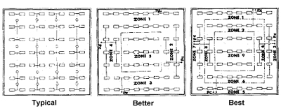
Figure 10. Smaller zones increase flexibility and control accuracy, and able
the fixtures to be zoned according to gradients of daylight availability.
Courtesy of Better Bricks.
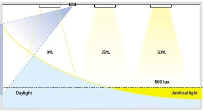
Figure 11. In this example, fixture rows are circuited parallel to the
window, enabling variable savings and light levels based on daylight
availability.
Courtesy of Leviton.
Zoning with DALI:
Daylight harvesting control applications may demand a high degree of
granularity of control zones for optimal energy savings and performance. Zoning
at the fixture level can present challenges with conventional wiring and analog
control in terms of cost, commissioning and maintenance.
Emerging technology, specifically digital dimming control systems based on the Digital Addressable Lighting Interface (DALI) protocol or proprietary protocol, enable practical individual fixture control. With digital dimming control, wiring is simplified because all fixtures are connected by a single two-wire bus, forming a lighting network of addressable ballasts that can be individual programmed or programmed in groups. The facility operator, in other words, can set the desired light level for each fixture. The lighting contours as described in the previous sidelighting and toplighting examples can be matched to the light levels of each fixture to provide the desired visual environment. Separate scenes can be programmed for different daylight conditions—dark, overcast and clear—allowing the daylight harvesting control system to respond to the range of daylighting conditions. The ability to fade gradually from one scene to the next allows lighting changes to be virtually unnoticed.
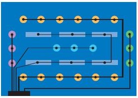
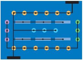
Figure 12a. Conventional controls wiring scheme. Five separate lead runs from the wall controller are required in this example, creating wiring complexity. If the system must be changed in the future, rewiring is required.
Courtesy of Universal Lighting Technologies.
Figure 12b. Digital network wiring scheme. All ballasts are connected to the same lead runs, simplifying the wiring required. Rezoning and adding controllers are also simplified.
Courtesy of Universal Lighting Technologies.
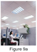
Placing the Photosensor
For a precise correlation between photosensor input and light level on the
task surface, the ideal location for the photosensor is at the task surface.
However, this is not practical because activities in the space would interfere
with the photosensor’s performance. For proper performance, photosensors are
typically mounted on walls, on the ceiling or integrated with light fixtures. In
sidelighting applications, the photosensor is typically placed on the ceiling
looking down on a representative task area. For skylighting applications, the
photosensor is often placed in a skylight looking up at the available daylight.
A leading cause of daylight harvesting project failures is improper placement of photosensors. Since the performance of the control system depends entirely on what the photosensor “sees,” proper placement is critical, especially in side-lighting applications, which rely on reflected, diffuse daylight, and where direct sunlight can affect the performance of photosensors. Even a slight change in location and orientation can affect the performance of photosensors.
The challenge is to orient the sensor in such a way that is measures reflected daylight in proportion to how it varies on the task surface. The ideal placement is such that the sensor has a high level of illumination from daylight, but is shielded from any exterior glare sources.
The photosensor should be placed so that it receives a representative sampling of daylight. Too broad a field of view for the sensor can result in detecting direct sunlight or light sources outside the control zone. Too narrow a view can make the sensor too sensitive to local changes in brightness. Use a light meter to measure light levels at potential locations before choosing the final placement. Otherwise, placement is highly dependent on the application characteristics.
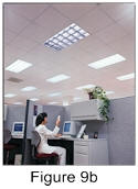
Closed-loop photosensors are generally mounted on the ceiling so that it views a representative area—including the lighted area that it is controlling. They should not directly view the window or a pendant fixture. Closed-loop systems must be set up with light level readings under both daytime and nighttime or dusk (or approximating dusk—i.e., with blinds closed) conditions
Open-loop photosensors are also typically mounted on the ceiling, but look toward the window or up into a skylight well to view incoming daylight but not the lighted area being controlled. Open-loop systems tend to be easier to set up, requiring a light level reading only during the daytime.
Regardless of technology or product selected, follow the manufacturer’s instructions for placing a photosensor.
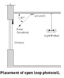
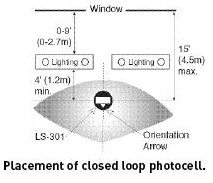
Figure 13. Placement of open loop photosensor.
Figure 14. Placement of closed loop photosensor.
Courtesy of Watt Stopper/Legrand.
Establishing Setpoints
Daylight harvesting controls dim or switch to maintain a target setpoint.
Determining the setpoint is a critical design decision that can be fine-tuned
during commissioning.
The setpoint should be higher than the designed maintained light level. Higher setpoints can decrease energy savings but are likely to increase user acceptance. Studies indicate that people like light levels to increase as daylight contribution increases, that their awareness of switching or dimming decreases as overall light level increases, and that they tolerate light level dynamic lighting changes typical with daylighting as long as their task lighting needs are met. Typical daylighting practice allows daylight levels to be 2-3 times higher than the design light level, so higher levels of daylight are likely available.
[an error occurred while processing this directive] In dimming applications, recommended practice is that dimming not begin until the daylight contribution is 150% of the design light level. In switching applications, recommended practice is that switching not occur until the daylight contribution is 150-200% of the level to be reduced.
Setpoints and Switching:
Switching interior lighting as a function of available daylight is
inexpensive but intrusive. For this reason, photoswitches should provide
switching at “safe levels” with a wide deadband to minimize nuisance switching.
Some photoswitches are also available with time delays to further minimize
nuisance switching by ensuring that the system is slow to respond to sudden
daylight changes. These operating parameters are set in the field during
calibration of the daylight harvesting control system. In this sense,
photoswitches are like occupancy sensors, with adjustable sensitivity and time
delay response, that respond to measured light levels instead of occupancy.
Photoswitches should have two setpoints, which are separated by deadband, and two time delays. The deadband defines sensitivity of the switching response to daylight by creating a buffer between the threshold levels (ON setpoint and OFF setpoint). The shorter the deadband between the two setpoints, the greater the sensitivity. If the deadband is too small and daylight conditions are variable (e.g., intermittent cloud conditions), the controls may switch on and off frequently during the day, which can reduce lamp life while annoying occupants.
When daylight increases, the monitored light level increases, first above the ON setpoint, but still within the deadband, so the lights stay on. As the daylight increases further and the light level rises above the OFF setpoint, the lights are switched after the time delay and remain OFF until the light level falls below the ON setpoint and the second time delay lapses. If the photoswitch senses the electric light it is controlling, then the deadband should be larger.
Usually, the time delay for switching the lights ON is very short to ensure users have adequate light levels, while the time delay for switching the lights OFF is longer to avoid frequent nuisance switching due to variable daylight conditions. For example, the ON time delay might be 20 seconds, while the OFF time delay might be 20 minutes.
Determining the deadband and time delay not only requires understanding of local daylight conditions, but also a decision about tradeoffs between energy savings and occupant acceptance. As deadband and time delay increase, energy savings and the likelihood of nuisance switching will decrease.
Setpoints and Closed-Loop Systems:
If a closed-loop system is used, the deadband must be adjusted to account
for the removal or a large portion of light level that was being contributed by
the electric lighting system. Otherwise, as daylight increases past the ON
setpoint, the lights may switch, which significantly decreases light level,
which—if it falls below the OFF setpoint, will cause the lights to switch back
on again. To avoid cycling, the deadband must be larger than the contribution
from the electric lights that will be removed during switching.
Closed-loop systems must work with a sliding setpoint control; as daylight increases, the setpoint also increases, so that the light level is maintained or even increased as daylight increases.
Figure 15. Switching interior
lighting as a function of available daylight is inexpensive but intrusive. For
this reason, photoswitches should provide switching at “safe levels” with a wide
deadband to minimize nuisance switching. Some photoswitches are also available
with time delays to further minimize nuisance switching by ensuring that the
system is slow to respond to sudden daylight changes. These operating parameters
are set in the field during calibration of the daylight harvesting control
system.
Courtesy of Gentec.
Commissioning
When daylight harvesting
systems fail, it is often because they are not properly installed and
commissioned. Daylight coverage in each space is virtually unique and therefore dimming
solutions typically will not meet the design intent right out of the box.
Provide specific guidelines and expectations for checkout and verification of
the controls. Specify commissioning services as a separate item, to be bid
separately. Some manufacturers provide commissioning support.
Table 1. Recommended calibration and commissioning activities for a daylight
harvesting control system.
Courtesy of Lighting Controls Association.
Applications
Private Office
This application is an enclosed single-occupant office in which primary
tasks include computer work, meetings and reading. Daylight enters through a
window, generating energy-savings opportunities with daylight harvesting
controls in addition to automatic shut-off. In this space, automatic daylight
dimming is provided using dimmable ballasts connected to a photosensor. For
automatic shut-off, a ceiling-mounted occupancy sensor is also installed.
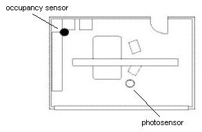
Figure 16. Private office.
Courtesy of Watt Stopper/Legrand.
Gymnasium
This application is a gymnasium with skylights and T5HO hi-bay light
fixtures, in which primary tasks include classes and games during both daytime
and nighttime hours. Daylight entering through the skylights provide
energy-saving opportunities with daylight harvesting control. In this space,
bi-level or multi-level switching can be employed, coupled with automatic
shut-off to comply with energy codes.
If the fixtures are 4-lamp, each fixture will have two 2-lamp ballasts
controlled on separate circuits, enabling bi-level switching (ON, 50% and OFF).
If the fixtures are 6-lamp, each fixture will have three 2-lamp ballasts
controlled on separate circuits, enabling multi-level switching (ON, 66%, 33%
and OFF).
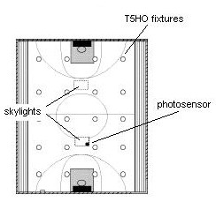
Figure 17. Gymnasium.
Courtesy of Watt Stopper/Legrand.
Classroom
This classroom—with primary tasks including reading, computer work, testing
and presentations—receives daylight from multiple sources, presenting
energy-saving opportunities with daylight harvesting control in addition to
automatic shut-off. Manual override capability will also be provided for user
control of light levels. The direct/indirect pendant fixtures are divided into
two zones in which dimmable ballasts enable continuous dimming. Both are
controlled by a ceiling-mounted occupancy sensor and local override easily
accessible to the teacher.
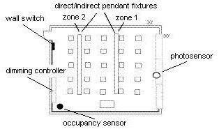
Figure 18. Classroom.
Courtesy of Watt Stopper/Legrand.
Learn More
Learn more by visiting the Lighting Controls Association at
www.aboutlightingcontrols.org
in particular its Education Express section, which features a free online course
about daylight harvesting control.
[an error occurred while processing this directive]
[Click Banner To Learn More]
[Home Page] [The Automator] [About] [Subscribe ] [Contact Us]