December 2008
![]()
AutomatedBuildings.com
[an error occurred while processing this directive]
(Click Message to Learn More)
December 2008 |
[an error occurred while processing this directive] |
|
Modbus is popular for its simplicity. Because so many users with Modbus knowledge are in the field and because a Modbus-IDA association backs this open standard, it will continue to remain popular. |
|
Part 1 Published in our September Issue
Introduction
In this second part of a two-part series on Modbus, we will discuss two implementations of the Modbus Protocol that were introduced in our previous article. The first implementation is the traditional implementation of Modbus over a serial line. The second implementation is more modern with Modbus operating over a TCP/IP network. Both implementations remain popular.
|
|
|
|
|
|
|
|
|
|
|
|
|
|
|
|
|
|
|
|
|
[an error occurred while processing this directive] |
Modbus over Serial Line
Modbus.org has released a Modbus over Serial Line Specification and Implementation Guide V1.02 that provides guidance when using Modbus with serial links. As mentioned in our previous article, Modbus was originally intended to be used with point-to-point EIA-232C interfaces with the master being a Human Machine Interface (HMI) and a PLC as the slave. Multiple slaves connected to one master would then require multiple links which is inconvenient and expensive. It would be only natural to change the point-to-point link to a multipoint serial infrastructure such as EIA-485 which would allow one master to communicate to multiple slaves over a common serial line. This approach is encouraged in the Modbus.org document, but not mentioned in the original Modicon Modbus Protocol Reference Guide.
Three Layer Model
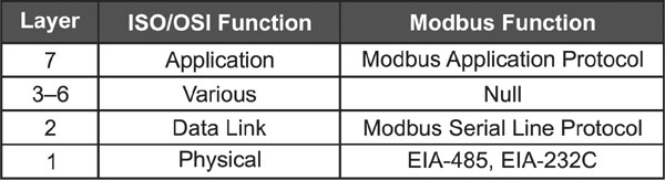
Table 1. Modbus over Serial Line uses a three-layer model.
Instead of the traditional seven-layer ISO Open Systems Interconnection Reference Model, the Modbus over Serial Line model is collapsed to three layers as shown in Table 1. At the top is the application layer that was discussed in part 1. This is called the Modbus Application Protocol or simply the Modbus Protocol. Layers 3�6 are not used � instead, relying upon the application layer to ensure end-to-end delivery of a message. The data link (layer 2) is occupied by the Modbus Serial Line Protocol. Finally, the physical layer (layer 1) allows for either the EIA-232 or EIA-485 implementation. With only three layers, Modbus over Serial Line is easier to understand than other industrial protocols. Since the Modbus Application Protocol was discussed in part 1, it will not be repeated here. Instead, only the data link and physical layers will be discussed.
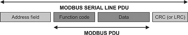
Figure 1. A slave address field and error check wrap around a Modbus PDU.
Data Link Layer
Much about the Modbus over Serial Line Protocol Data Unit (PDU) was mentioned in part 1 but will be summarized below. Referring to Figure 1, note that the PDU consists of four elements. In the middle is the Modbus PDU consisting of a function code and data. Most Modbus implementations only use a subset of all the available function codes. The data structure may change depending upon the function code. Wrapping the Modbus PDU is an address field and an error check field. The address field only contains slave addresses or the broadcast address. The master address is not required and not referenced since this is a master/slave protocol with commands originating from a unique master.
As mentioned in part 1, the actual framing of Modbus over Serial Line messages depends on whether ASCII or RTU transmission mode is used. RTU is the most popular mode and is shown in Figure 2. It is a very compact frame with only one byte reserved for the slave or broadcast address, one byte for the function code and two bytes for the CRC error check. A single byte carries the function code. Notice that there is no end-of-frame sequence. With RTU, end-of-frame is indicated by 3.5�4.5 character times of silence. The largest frame only occupies 256 bytes. With RTU each byte is sent using 11 bits. Each data-byte requires eight bits. There is one start-bit, one stop-bit and one parity-bit. If parity is not used, another stop-bit is sent in its place. If parity is employed, it can be odd or even.
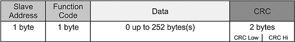
Figure 2. RTU framing is more condensed than ASCII framing.
The ASCII message format in Figure 3 requires two bytes for the slave address as well as for the function code. Unlike RTU, the ASCII frame uses a two-byte LRC for the error check field. The advantage of the ASCII format is that it is human readable. Notice that there is an end-of-frame sequence composed of carriage return and line feed (CRLF). Inter-frame spacing is not critical. Data is represented as a hexadecimal value coded as ASCII. Therefore, only 7 bits are required for every ASCII character, but two characters are required for each byte of data. One start-bit and one stop-bit are used. If a parity-bit is used, either odd or even parity can be sent. If no parity is sent, then another stop-bit is sent. This means each byte in ASCII is sent as 10 bits.

Figure 3. ASCII framing requires start-of-frame and end-of-frame characters.
Physical Layer
The original Modbus protocol called for a point-to-point EIA-232C link between a host computer and a PLC. This option remains today. But the Modbus over Serial Line specification encourages the use of the multipoint EIA-485 standard � supporting up to 32 devices over a common bus. This can be implemented with either a two-wire or four-wire cabling configuration. With any of the serial line implementations, a wide range of baud rates from 1.2 kbps to 115 kbps are allowed, but all implementations must at least support 9.6 kbps and 19.2 kbps. The default rate is 19.2 kbps.
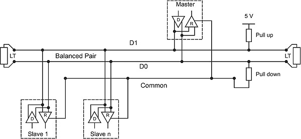
Figure 4. A two-wire serial line implementation actually requires three wires.
Two-Wire Network
Figure 4 shows a recommended two-wire interface for EIA-485 networks with applied line polarization. As expected, there is one master transceiver and multiple slave transceivers connected to a common 2-wire bus with the wires labeled D1 and D0. At a minimum, a total of 32 devices must be supported. With a 2-wire bus, the output of the transmitter is directly tied to the input of a receiver at each device. Even though this is called a 2-wire bus, there is a common reference connection labeled common. Each device must share its common with all other devices on the bus to ensure that the maximum common-mode voltage rating of the device is not exceeded. The line polarization network (consisting of a pull-up and pull-down resistor) is shown near the master, but its location is not a requirement � only a recommendation. Line polarization is used to force the bus into a known state when no drivers are active. EIA-485 receivers require a 200 mv failsafe bias to ensure they detect a floating line as an �off� state. This is why line polarization is typically referred to as failsafe bias. At each end of the bus are line terminators (LT) to match the natural impedance of the bus. The pull-up and pull-down resistors interact with the two termination resistors to create the failsafe bias. The Modbus over Serial Line specification recommends that the pull-up and pull-down resistors have values between 450 and 650 ohms, and that only one network is used. This assumes that failsafe bias is needed at all. Some transceivers have built-in bias so external bias is not needed.
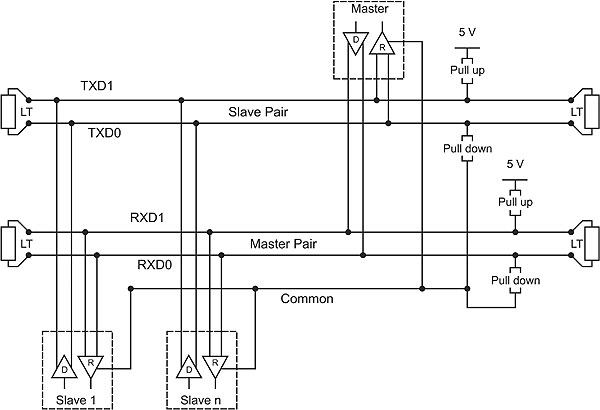
Figure 5. A four-wire serial line implementation actually requires five wires.
[an error occurred while processing this directive] Four-Wire Network
Figure 5 shows a recommended four-wire interface still using EIA-485 devices. The transmitter of each device is separated from the device�s receiver. The master has its transmitter connected to all the slaves� receivers while all the slave�s transmitters are connected to the master�s receiver. Failsafe bias and termination are still used � but their requirements are doubled in a four-wire network. Even the four-wire arrangement requires a �fifth� wire and that is the common.
Although the Modbus over Serial Line specification supports both a 2-wire and 4-wire arrangement, the 2-wire implementation is the most popular. Although it is possible to have a full-duplex link with 4 wires, the Modbus protocol is strictly half-duplex. The master imitates commands to a particular slave while awaiting the slave�s response. This is handled quite effectively with a 2-wire implementation.
Modbus TCP
The Modbus protocol continues to survive in an automation world more interested with connecting to Ethernet networks and more specifically, IP/Ethernet networks. Modbus.org authored the Modbus Messaging on TCP/IP Implementation Guide V1.0b for this very purpose. Instead of a three-layer model that was used for Modbus over Serial Line, a five-layer Internet model was used for Modbus TCP as shown in Table 2. Instead of a long discussion on physical and data link layer issues, the standard only needs to point to the 1500 page IEEE 802.3 standard. There is no mention of how to physically attach stations or what cabling or connectors to use. This messaging standard only talks about how a Modbus PDU (consisting of a function code and data) is encapsulated into a higher level protocol.
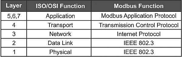
Table 2. Modbus TCP uses a five-layer Internet model.
Another significant change (shown in Figure 6) is that the Modbus bus is actually an IP bus. The physical and data link layers are not specified. Instead of having one master attached to multiple slaves, the terms client and server are used. Clients could be HMIs or PLCs, while servers could be input/output racks. Like a master, clients initiate commands to a server. Like a slave, servers respond to client commands. However, the proper terminology with client/server communications is that clients initiate requests with servers providing responses. It is actually a bit more involved than that.
A Request is sent by the client to initiate a transaction.
An Indication is sent by the server to confirm that a request was received.
A Response is sent by the server to comply with the client request.
A Confirmation is sent by the client to acknowledge receipt of the response.
What is significant in this model is that several clients can reside on the IP network and access a common set of servers. This is a fundamental change in how the Modbus protocol works. There is no single master controlling a defined set of slaves. Any number of clients can access any number of servers. Is it possible to have conflicts with clients making contradictory requests of a particular server? Yes, that is the risk this model presents with its newly gained flexibility.
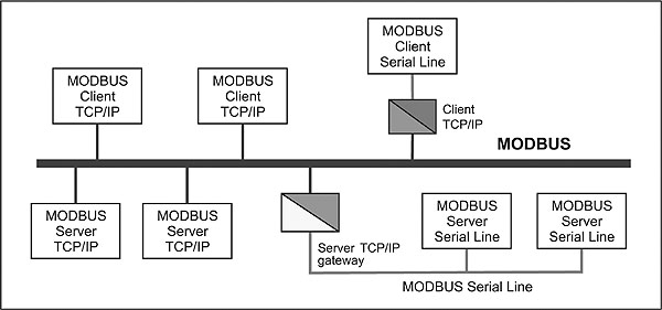
Figure 6. Instead of using master and slaves, the Modbus TCP model uses clients
and servers.
The MBAP Header
Figure 7 shows how a new Modbus TCP/IP Application Data Unit (ADU) is formed. The traditional Modbus PDU of the Modbus over Serial Line method is still present. The function code and data definitions remain intact. What is appended to this PDU is a Modbus Application Protocol (MBAP) header details of which are shown in Figure 8. The Transaction Identifier is supplied by the client and used to keep track of specific requests. The server is to send back the same identifier with its response. The client is allowed to send multiple requests of a server without waiting for individual responses. The Protocol Identifier would allow support for multiple protocols. For Modbus the value is zero. The Length field identifies the length of all remaining fields including the Modbus PDU fields. Finally, the Unit Identifier provides the address of a Modbus Serial Line slave that must be accessed through a gateway. With Modbus TCP clients and servers, station addressing occurs by using IP addresses. However, if a Modbus slave is attached to a serial line, the actual slave address needs to be specified. The gateway address would then be an IP address. In order to send the ADU over TCP, a registered TCP port number must be used. Modbus.org registered port 502 for this purpose.
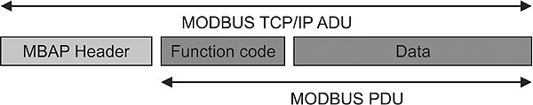
Figure 7. The Modbus Application Protocol header is added to the Modbus PDU.
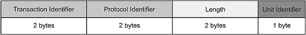
Figure 8. The MBAP header is seven bytes long.
Summary
Modbus is popular for its simplicity. Because so many users with Modbus knowledge are in the field and because a Modbus-IDA association backs this open standard, it will continue to remain popular.
References
Modbus Application Protocol Specification V1.1b, http://www.Modbus-IDA.org, December 28, 2006
Modbus over Serial Line Specification and Implementation Guide V1.02, http://www.Modbus-IDA.org, December 20, 2006
Modbus Messaging on TCP/IP Implementation Guide V1.0b, http://www.Modbus-IDA.org, October 24, 2006
Modbus Protocol Reference Guide Rev. J, http://www.Modbus-IDA.org, June 1996
[an error occurred while processing this directive]
[Click Banner To Learn More]
[Home Page] [The Automator] [About] [Subscribe ] [Contact Us]