Hot and Humid Climates
|
February 2012 |
[an error occurred while processing this directive] |
| Chilled Beam Application & Control Hot and Humid Climates |
| Articles |
| Interviews |
| Releases |
| New Products |
| Reviews |
| [an error occurred while processing this directive] |
| Editorial |
| Events |
| Sponsors |
| Site Search |
| Newsletters |
| [an error occurred while processing this directive] |
| Archives |
| Past Issues |
| Home |
| Editors |
| eDucation |
| [an error occurred while processing this directive] |
| Training |
| Links |
| Software |
| Subscribe |
| [an error occurred while processing this directive] |
Overview
It is a misconception that chilled beam technology cannot be utilized in hot and humid climates. With proper design and control, chilled beams can be a viable alternative to traditional HVAC systems, regardless of location. This engineering bulletin will provide a basic overview of chilled beam application and will discuss some of the methods utilized to ensure trouble free operation. Also discussed will be first cost and energy savings benefits that may be realized when chilled beam systems are employed as well as ways to measure and verify system performance in order to optimize results
Concepts and Benefits
Chilled beam systems use water as well as air to transport thermal
energy throughout a building. The chilled beam includes a hydronic coil
which provides heating or cooling to the space. Either 2-pipe or 4-pipe
designs are available. The benefit of the 4-pipe configuration being
that some zones can receive cold water for space cooling while other
zones simultaneously receive hot water for space heating.
Chilled beams come in both active and passive configurations, both
require the building ventilation and latent loads be decoupled and
addressed separately. Dry, conditioned air is supplied to the space to
handle these loads, as well as offsetting some of the space sensible
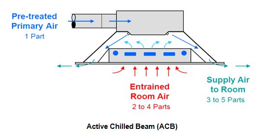
load. When conditioned primary air is supplied directly to the chilled
beam itself, the device is called an “active” chilled beam (ACB). The
primary air travels through nozzles in the beam where its velocity is
increased, inducing additional room air through the beams coil. This
induced air mixes with the primary air and is discharged back into the
space through slots along the beam.
Passive chilled beams (PCB) are not directly supplied with primary air
and rely completely on natural convection to provide their sensible
capacity. They will not be specifically addressed in this paper as they
have limited application in hot and humid climates although they can be
used when needed to supplement a load requirement where an active beam
falls short.
Chilled beams are ideal for applications with high space sensible cooling loads and should be installed where the tightness of the building envelope is adequate to prevent excessive moisture transfer. Space moisture gains due to occupancy and/or processes should also be moderate. Successful installations of chilled beam systems have included the following applications, regardless of local climate.

As a “decoupled” system, where hydronic-based heating or cooling devices are integrated with the primary air ventilation system, this allows for individual optimization of all heating, cooling and ventilation functions with unique opportunities for savings in energy, space and maintenance, such as:
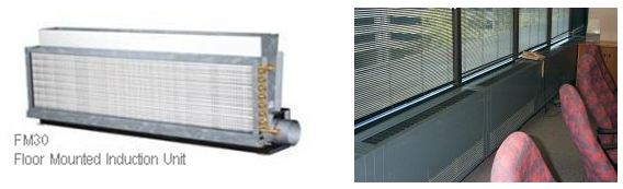
Upgrade & Retrofit of Existing “Induction Units”:
No conversation on chilled beams would be complete without mentioning
the opportunity for their use in retrofitting older induction unit
installations. Very popular in the 1950s and 1960s, induction units
were used in large buildings where space was at a premium and the small
primary air ductwork used with the induction system was an advantage in
reducing mechanical space requirements and floor heights. Induction
units were typically mounted on the floor (up against an outside wall)
in the building’s perimeter zones and then concealed under enclosures
built to suit the size of the units selected.
The energy crisis of the 1970s forced induction systems into disfavor.
There were energy cost concerns as the old induction units required
very high inlet static pressure (often 1.5 – 3.0 in. w.c. or more)
which imposed a significant fan energy penalty. Old induction units
produced relatively high noise levels and because they were located in
the occupied space, provided poor air distribution patterns which
promoted drafts. These units were often pneumatically controlled and
offered none of the comfort and efficiency advantages of a modern
building automation system (BAS). They could also be a constant
headache for maintenance personnel.
Existing buildings which utilize induction units have some real
infrastructure issues when it comes to renovation. Small, high velocity
primary OA risers, existing piping and relatively low floor to floor
height can make the conversion to a more traditional HVAC system cost
prohibitive or impractical. Many such buildings have been abandoned in
favor of new construction, while there are still thousands of these
older buildings now in need of updating. Rather than simply replacing
the old induction units with like units or renovating the entire HVAC
system, there is often an opportunity to significantly improve the
performance of these old induction system through the use of new
chilled beam technology while re-using much of the building’s existing
infrastructure (ductwork, piping, etc.).
[an error occurred while processing this directive] Considerations in Hot & Humid-Climates:
Humidity becomes an issue if the surface of any cooling coil or unit
panel dips below the surrounding air’s local dewpoint. When the air in
contact with this cold surface falls below its dewpoint temperature,
there is a certainty of condensation forming.
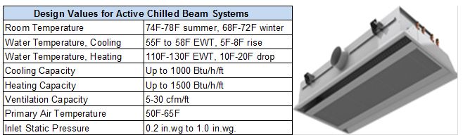
With chilled beams (and other A/C devices) comes a challenge to prevent condensation formation on any cool surfaces. This is addressed by the primary air system which supplies dry air to the beam to handle the space latent and ventilation loads and will limit the indoor dewpoint temperature, typically below 55°F. How dry this air must be depends on the quantity of primary air delivered, as well as the load in the space. Chilled water, supplied to the beam to handle space sensible loads, should be provided at temperatures above the local dewpoint so as not to promote the formation of condensate. Chilled water temperatures are typically delivered at 58°F-60°F and when properly controlled will keep beam surface temperatures elevated above the local dewpoint.
There are factors which help provide relief in situations where a
surface may momentarily dip below the local dewpoint temperature. A
space will generate a specific latent load (from internal sources)
which is then available to accumulate as condensate on any cooled
surface. When this moisture is spread across the entire surface area of
a coil or panel there is a limited amount of condensate that can form.
Even if cool surfaces in the space are left uncontrolled, they are
likely to be only slightly below the space dew point which also limits
the amount of condensate that will result.
Penn State Professor Stan Mumma, PhD., P.E., and Fellow ASHRAE (2002) performed various studies on chilled ceiling panels (the chilled beam’s predecessor). In these studies the surface temperature of the chilled ceiling panels were reduced, or space latent loads increased substantially beyond their design perimeters. His findings conclude that the formation of condensation in environments with chilled ceilings is a slow process and one that can be avoided by sound design and control. A review of his work will help provide proper perspective to the problems and risks associated with the installation of any cooling device that will come in contact with air.
Control Strategies:
Primary air flow rate can be controlled by a fully self-contained
volume flow limiter (VFL) which requires no power or control
connections and may be field set to maintain a volume flow rate to the
beam. VFL’s are recommended for use on beams fed by an air handling
unit that is also supplying VAV terminals. The VFL compensates for
system pressure changes to maintain the beam’s design airflow rate.
Room temperature control is primarily accomplished by varying the water
flow rate or its supply temperature to the chilled beam coil in
response to a zone thermostat signal. Modulation of the chilled water
flow rate typically produces a 7°F to 8˚F swing in the beam’s supplied
air temperature, which affects a 50 - 60% reduction in the beam’s
sensible cooling rate. This is usually sufficient for the control of
interior spaces (except conference areas) where sensible loads do not
tend to vary significantly. If additional reduction of the space
cooling is required, the primary air supply to the beam can be reduced.
In any case, modulation of the chilled water flow rate or temperature
should be the primary means for controlling room temperature as it has
little or no effect on space ventilation and/or dehumidification. Only
after the chilled water flow has been discontinued should the primary
airflow rate be reduced. Note: The chilled beam along with its primary
air and water transport systems can be slightly oversized when there is
a concern of peak load variations above design.
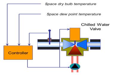
As long as the space dew point temperature can be maintained within a
reasonable range (+/- 2°F ) and the chilled water supply temperature is
at (or above) this value, condensation will be avoided on chilled beam
surfaces. Should there be periods when room humidity conditions
drift or rise above design, and a dewpoint sensor detects condensate
formation (or the potential), typical control action would be to
modulate flow to the beam or reset the chilled water supply temperature
(higher) in order to reduce beam capacity and increase surface
temperatures. An alternative to this is to simply shut off the CHWS to
the zone and allow the conditioned primary air (if sized with excess
capacity) to assist in returning the space to its proper humidity
level. This is not recommended in humid climates as thermal control may
be lost resulting in a space that can’t be occupied
comfortably.
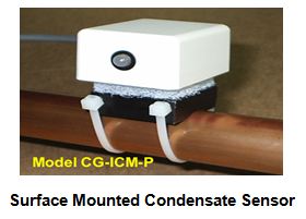
Control Sensors:
Preventing the formation of condensate on chilled beam surfaces must be
addressed, especially in hot and humid climates. Proper system design
combined with measurement and control of space humidity will help
ensure satisfactory performance. The following will discuss a few of
the more common control sensors used to help make sure requirements are
met.

In addition to the more traditional sensing devices described above, a
variety of high-performance sensors are available when more demanding
requirements are presented. These include Impedance Dew Point Sensors,
Chilled Mirror Sensors, and Dark Spot Optical Hydrocarbon Dewpoint
Detection.
Monitoring & Measurement
What gets measured gets done and what doesn’t get measured gets ignored. Maintaining local dewpoint temperature may be the single most important factor in ensuring trouble free operation. But as mentioned earlier, there are additional factors which play a role in providing indoor environmental quality and comfort. No matter how good the design, control and installation of the chilled beam system is, it is all for naught if “real-life” performance is not measured and verified in order to assure that the desired results are delivered.
Facility managers need to know at a glance whether or not they are
maintaining critical space dewpoint levels and comfortable and
healthful conditions in their buildings. By programming space sensor
readings into a Building Automation System, a facility manager can
easily generate a measurement tool that provides a numeric “score” of
how well the buildings HVAC system is performing. These readings can be
given a grade between 0-100 (based on how close they are to set point)
and rolled up into one overall building or zone grade. “100” would be
perfect and any numeric score below this would indicate degradation in
performance.
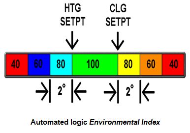
Automatic Logic’s Environmental Index (EI) doesn’t require a facility
manager to manually review individual temperature, humidity or CO2
readings to determine the HVAC systems compliance to comfort set
points, nor does it require manual calculations be performed to score
the results. Space conditions are automatically graded, color coded and
displayed in real time on a thermograph of the building floor plan
which allows a viewer to instantly recognize any areas of concern.

Any condition that can be read and sent to the EI (temperature,
humidity, CO2, dewpoint, etc.) can be scored and indexed for the
operator to visually keep track of. By using this color format, the ALC
Environmental Index is intuitive and as easy as obeying a street
traffic light.
It is vital to be proactive to potential humidity issues which
will result in the loss of space control, with one quick glance at the
indexed floor plan a facility manager can make an instant assessment of
space dewpoint and other thermal comfort conditions throughout the
building. Should an unacceptable condition be detected immediate action
can be taken in order to remedy the situation before it becomes a
problem. Environmental Indexing can provide up to the minute trending,
recording and notification of all thermal (and even energy) related
information, providing owners or facilities managers with measurement
and verification that documents HVAC system performance. EI can even be
utilized in existing buildings where sensors and controls are already
in place.
[an error occurred while processing this directive] Implementation:
The key to a successful chilled beam installation starts with a design
that provides fulfillment of the buildings heating and cooling needs.
Detailed analysis of sensible and (particularly) latent loads tied to
internal sources, ventilation and infiltration must result in equipment
and transport systems that are sized and installed to handle loads so
proper environmental set points can be maintained. The BAS system and
control strategy implemented will result in a system that will realize
the design intent. Measurement and verification will ensure trouble
free operation and that the building achieves optimum environmental
comfort and energy performance.
Chilled beams may require a bit more design consideration than other, typical HVAC systems but as long as important details are not overlooked, they can be successfully applied in any climate. Superior performance comes from combining the experience and expertise of all parties involved in the building’s design.
Please feel free to contact us for additional guidance and support on
chilled beams, or any other building application and control
requirement.
AutomatedLogic Houston
David N. Schurk, DES., LEED AP.
Director of Healthcare Accounts
I can be contacted at davids@uescontrol.com or by phone at 281-702-3503
“To meet our energy challenge requires the most important energy of all….human creativity”
References:
1. Automated Logic Control System Design and Application Manual.
2. Automated Logic WebCTRL Applications Manual.
3. TROX Chilled Beam Design Guide.
4. Chilled ceilings, addressing the concerns of condensation, Mumma, SA (2002).
5. Ceiling radiant cooling panels, Mumma, S.A (2006.)
6. Price Engineers HVAC Handbook.
7. DADANCO, Breathing Life Into Your Buildings.
[an error occurred while processing this directive]
[Click Banner To Learn More]
[Home Page] [The Automator] [About] [Subscribe ] [Contact Us]
 David Schurk, DES., LEED AP.