October 2004
![]()
AutomatedBuildings.com
[an error occurred while processing this directive]
(Click Message to Learn More)
October 2004 |
[an error occurred while processing this directive] |
|
|
Brian Jones, |
The S4 Group recognized the customer requirements to extend and expand the capabilities of the Johnson Controls Metasys N2 field bus and developed our N2 Router product line to meet that need. Now that we have successfully completed a large part of the testing for our N2 Switch, the entry level product of the family, and the OPC N2 Router in undergoing initial customer testing we thought we would share some of our experiences with our customers and integration partners. When we started the project one of our early priorities were to set up a test lab that provided the flexibility that would be needed to thoroughly test our systems in an open environment. To that end, we need to be able to quickly insert or remove any device in the test configuration with a minimal amount of effort and associate it with any N2 network. What we decided on was using the tried and true modular telephone jack system with RJ-11 (4-pin) connectors. This worked out extremely well for the initial product testing in our lab environment and has proven to be invaluable as we moved into testing multi-vendor equipment that might have never before been used in a N2 networking environment.
|
|
|
|
|
|
|
|
|
|
|
|
|
|
|
|
|
|
|
|
|
|
|
[an error occurred while processing this directive] |
The basic technology of a N2 network is defined around the ubiquitous RS-485 set of data communications standards. The N2 network runs at 9600bd, 8 data bits, and no parity and in half-duplex mode. No surprises here. This is very standard data communications stuff and the RS-485 technology is very well known and well understood by industry. The terminology N2(+) and N2(-) has been adopted by Johnson Controls for the two data wires in a N2 network. A third wire provides a reference.
One of our early design goals for the N2 Router product family was in acknowledgment that we are not a hardware manufacturer, did not want to be, and therefore needed to design our software to work with standard off the shelf hardware platforms and networking products. After all we have been running around for the last couple of years touting the benefits of open systems so we couldn’t do anything proprietary ourselves! What we found surprising was the general amount of confusion and conflicting information we found in naming conventions and terminology relating to the two data lines associated with commercially available off the shelf half duplex RS-485 implementations. If people talk about the N2(+), Data (+), Positive, or the (B) side of the connection it may or may not mean the same thing.
Since a lot of our initial testing has been done with B&B Electronics devices we sought and expert opinion from them and this is what we heard from Mike Fahrion. Mike’s initial response was true to character “Ah this is a sore subject”. Then he proceeded with an explanation of the situation. B&B follows the one and only standard (comes from EIA-485). A and B are the correct designators. Definition is that B is more positive than A on an idle network. So, for equipment that uses the +/- convention, A usually equals "-" and B usually equals "+". That's probably how it works 80-90% of the time. The sure way to tell is with a scope (meter is ok). The challenge is that an idle 485 network is really floating unless biasing resistors are installed (because the driver is tristated and the receiver is always high impedance). If the bias resistors are correct, you'll measure a positive voltage on B with respect to A when the line is idle.
The long and the short of this is that you can’t always believe what you read in RS-485 product documentation. Testing of each device in a live N2 network is critical. As a result of all this, we decided that we needed to define a standard for our Lab and needed to take a very practical, and pragmatic, approach to introducing new devices into our test environment. To that end, we decided on the following standard for cabling our test N2 networks. As mentioned earlier we are using RJ-11 jacks and connectors so we settled in on the following internal wiring standard using CAT-5 or telephone station wire.
|
RJ-11 Pin |
Wire Code |
Function |
|
3 |
Red |
N2(+) |
|
4 |
Green |
N2(-) |
|
5 |
Yellow |
Reference |
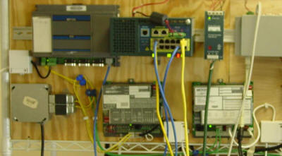 At each N2 device we mount a dual RJ-11 jack with the
two jacks being wired in parallel. Then, using custom wired patch cables, any
device can be inserted or removed from any of our N2 networks, in any order
desired, in a matter of seconds. We have started publishing technical notes to
assist our customers and integrators in implementing our N2 Router product
family, and in integrating networking devices that we have tested, into Metasys®
N2 network environments. Since we are promoting open systems and standards we
won’t endorse a specific product as being superior to any other.
At each N2 device we mount a dual RJ-11 jack with the
two jacks being wired in parallel. Then, using custom wired patch cables, any
device can be inserted or removed from any of our N2 networks, in any order
desired, in a matter of seconds. We have started publishing technical notes to
assist our customers and integrators in implementing our N2 Router product
family, and in integrating networking devices that we have tested, into Metasys®
N2 network environments. Since we are promoting open systems and standards we
won’t endorse a specific product as being superior to any other.
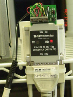 The first device that we worked extensively with is
the B&B Electronics 485TBLED RS-232 to RS485 converter. This has turned out to
be a workhorse in our test labs. Although for field work, particularly when long
cable runs or building-to-building links are made, B&B Electronics recommends
using the optically isolated version of the product (model 485OTLED). This will
give you the best reliability and robustness in the network design. Initially,
we purchased it to use with the PCs running the Johnson Controls N2 simulator
and other tools used in the Metasys Compatibility program. As testing progressed
we found that it was a very handy device that allowed us to utilize the built in
ports on PCs we are using for testing the software only version of our N2 Router
as target N2 networks. For details about how to the 485TBLED to your N2 network
please see our technical note. Remember, these notes will be written in the
context of our standard RJ-11 telephone jack wiring scheme for the S4 test lab.
The first device that we worked extensively with is
the B&B Electronics 485TBLED RS-232 to RS485 converter. This has turned out to
be a workhorse in our test labs. Although for field work, particularly when long
cable runs or building-to-building links are made, B&B Electronics recommends
using the optically isolated version of the product (model 485OTLED). This will
give you the best reliability and robustness in the network design. Initially,
we purchased it to use with the PCs running the Johnson Controls N2 simulator
and other tools used in the Metasys Compatibility program. As testing progressed
we found that it was a very handy device that allowed us to utilize the built in
ports on PCs we are using for testing the software only version of our N2 Router
as target N2 networks. For details about how to the 485TBLED to your N2 network
please see our technical note. Remember, these notes will be written in the
context of our standard RJ-11 telephone jack wiring scheme for the S4 test lab.
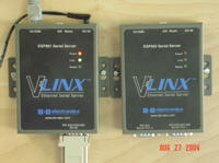
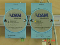 Next, we tested two Ethernet to RS-485 serial
servers, the Advantech ADAM 4571 and the B&B Electronics ESP901 with our N2
Switch. Both of these devices worked fine, both provide adequate configuration
and port mapping utilities, and both have multiport versions available which
work equally well with the N2 Switch. These devices would be used in remote
locations to extend multiple N2 networks across a customer’s Ethernet-based
intranet to a centrally located N2 Switch. There we would combine all of the
physical N2 networks into one virtual N2 network which would be presented to the
Johnson Controls supervisory controller.
Next, we tested two Ethernet to RS-485 serial
servers, the Advantech ADAM 4571 and the B&B Electronics ESP901 with our N2
Switch. Both of these devices worked fine, both provide adequate configuration
and port mapping utilities, and both have multiport versions available which
work equally well with the N2 Switch. These devices would be used in remote
locations to extend multiple N2 networks across a customer’s Ethernet-based
intranet to a centrally located N2 Switch. There we would combine all of the
physical N2 networks into one virtual N2 network which would be presented to the
Johnson Controls supervisory controller.
We have documented our findings in a series of technical notes that present the details necessary to successfully utilize these, and other, commercial off the shelf products in a Johnson Controls Metasys N2 environment. As our testing matures we will update these tech notes on a periodic basis. As we test additional devices they will be added to the library. They can be downloaded from our web site.
[an error occurred while processing this directive]
[Click Banner To Learn More]
[Home Page] [The Automator] [About] [Subscribe ] [Contact Us]