This demonstrates the power of Open-Source, both in software and now hardware.

Calvin Slater
Climatec
Contributing Editor
|
September 2019 |
[an error occurred while processing this directive] |
| Build
Your Own Edge Controller Backbone This demonstrates the power of Open-Source, both in software and now hardware. |
Calvin Slater Climatec Contributing Editor |
| Articles |
| Interviews |
| Releases |
| New Products |
| Reviews |
| [an error occurred while processing this directive] |
| Editorial |
| Events |
| Sponsors |
| Site Search |
| Newsletters |
| [an error occurred while processing this directive] |
| Archives |
| Past Issues |
| Home |
| Editors |
| eDucation |
| [an error occurred while processing this directive] |
| Training |
| Links |
| Software |
| Subscribe |
| [an error occurred while processing this directive] |
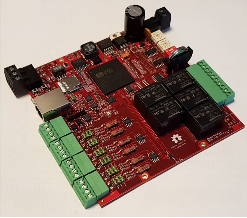
This is a Homemade,
Open-Source-Hardware Controller. It’s a complete single-board edge
compute device based on a 1GHz applications processor with 4GB of flash memory
and 512MB of RAM. It also has the following features:
This controller is not literally homemade. This particular prototype was fabricated and assembled by a contract manufacturer using plans I provided. There are many companies that provide such services here in North America as well as overseas. Many of them are completely vertically integrated and can offer full turn-key manufacturing. All you have to do is send them your design files (known as Gerbers) as well as a Bill of Materials, and they will send you back a complete functioning circuit board. They will fabricate your layered printed circuit board (PCB), source the board components for you, then assemble and test your device. You can order just one controller or one thousand!
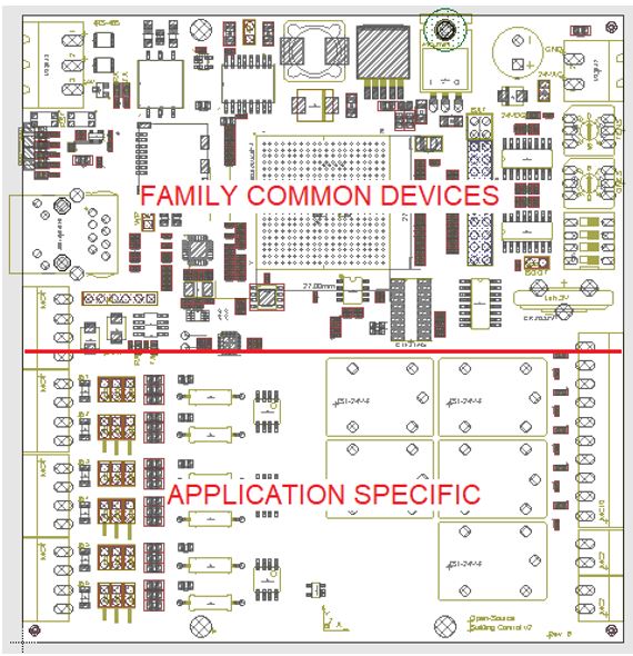
The design of this board, however, was done at home. The important thing to know here is that I am not an Electrical Engineer, nor do I design circuit boards professionally. Although there were some real EEs who were nice enough to review this design, the whole device layout was synthesized by a non-professional. The truth is the whole thing was relatively easy to do. The most complicated part would be the main processor and memory. However that was not a problem as this complex component is offered as a complete module. These processing packages are sometimes referred to as System on Module (SoM), or Computer on Module (CoM). The device for this particular board is called a System in Package or SiP. A SiP is basically the combination of several discrete processor parts, packaged into a single chip that is ready to use with no additional development. The hardest part has already been done. All that’s needed is to select what peripherals and interfaces should be connected to the controller. There are a lot of free reference materials available concerning how to connect and layout the rest of the components. As an example, one of the more difficult tasks was laying out the parts for the Ethernet interface. I was able to find several reference designs for this. I simply adapted the reference design layout to my board, and it worked.
[an error occurred while processing this directive]Doing
this would have not really been possible ten years ago. Much like
hobbyists began assembling their own custom desktop PCs in the ’80s and
90’s we are now entering the era of custom-built embedded controls.
Assembling your own embedded device is much the same as creating your
own desktop PC. You select the processor, peripherals, power source,
storage devices and enclosure and then assemble them all together. The
only real difference here is that the components are soldered to a
board rather than plugged-in. This demonstrates the power of
Open-Source, both in software and now hardware. For a few years now we
have been talking about how these hobbyist single-board computers can
be used for building automation. This became a reality when
Contemporary Controls released their first Open-Software Sedona
controller based on the Raspberry Pi in 2018.
Why
would someone want to build their own DDC controller? We will follow
this month’s theme of building backbones. To me building a backbone is
about creating the core communication and control infrastructure of a
building that will allow it to last for decades without a major
overhaul. It’s about trying to plan for a system that can be maintained
without reliance on the original vendor who installed it. It’s
difficult to predict what the future building automation architecture
will look like. Unless you are Ken Sinclair, you cannot predict the
future of controls. Open-Source hardware provides flexibility in this
way by giving you complete control of your edge devices. It gives you
the ability to add and remove device features at your discretion. With
Open-Hardware you have complete control of the devices form-factor and
peripherals. Want more inputs and outputs? Just add them! Or for
example, once the 5G revolution finally hits, you can incorporate a
cellular module into your device by yourself. As long as the basic
system has been validated and proven, adding and removing additional
capabilities is actually very easy.
What is the future for this particular board? My goals are the following:
[an error occurred while processing this directive]
[Click Banner To Learn More]
[Home Page] [The Automator] [About] [Subscribe ] [Contact Us]