April 2007
![]()
AutomatedBuildings.com
[an error occurred while processing this directive]
(Click Message to Learn More)
April 2007 |
[an error occurred while processing this directive] |
|
|
Bob Kern Over 25 years in product design and service of power conversion and control equipment. Power Service Concepts is the US distributor and service company for ExerTherm. |
In a data center not so far away, the manager is on a mission to discover every waiting problem before any have a chance to stop the primary mission - No Unscheduled Down Time. Of course we all imagine a perfect universe with no down time, no problems, and no unforeseen issues. Alas, we all know such a universe doesn’t exist, so back to reality.
|
|
|
|
|
|
|
|
|
|
|
|
|
|
|
|
|
|
|
|
|
[an error occurred while processing this directive] |
The mission of No Unscheduled Down Time has brought us from having to guess or rely on a particular person’s in depth personal connection with the equipment to where we are today. But technology hasn’t settled. After all, what manager wouldn’t want to know the state of equipment health, today, tomorrow and the next day, with no guessing and no intrusion?
Let's explore where we’ve came from, where we are, and where we are going – the Next Generation.
The 1st Generation - Him, he knows it the best……..
Some time ago the person that knew the data center equipment the best, walked their domain just looking, listening and feeling. That person knew the equipment better than his or her own person. Maybe they could feel the increase in heat radiating from a panel, hear the slower speed of a fan in a cabinet or slower response time from a server. Any little aberration that just didn’t seem right sparked investigations to make sure things were just fine. If a problem couldn’t be found, well, all they could do was wait and see and hope for more clues instead of a failure.
Of course this was far from perfect and was dominated by, “if it’s not broken, don’t fix it” and “keep an eye on it”. We had to wait for something to break, so we had something to fix. But this unscheduled down time, at its best, cost some lost revenue and didn’t damage equipment. At its worst, the wait and see attitude created an environment for fire or explosion.
This method of course was lacking in catching subtle problems before they became larger. It was a huge hazard for the person that had to feel around for a problem, open up panels and attempt to manually measure temperatures. All the data was empirical, subjective, and was done at a “convenient” time. Of course to check certain items or points, further disassembly was needed and the system had to be turned off, and didn’t always come back on as expected.
The one thing we learned during this time is that the most common failures had one thing in common, heat, or more so the increase in heat. If an item were going to fail; the bus bar joint, wire crimp, or connections within the PDU, the connection would increase in resistance. We would not see a “brown out” of the voltage, but would see an increase in radiated heat. As a connection first begins to fail, the temperature rise may only be 5 degrees and a month later another 5 degrees, for a total of 10. These minor increases in temperature are very hard to detect without comparative data. If we could catch that 1st increase in the temperature before it causes a degeneration of the quality of the connection, we could simply repair it and be fine.
So we needed a better way to quantify the temperature measurements.
The 2nd Generation - Thermography……..
To answer the need to collect quantifiable data fast Thermography became the selected defacto solution. Thermal imaging cameras are expensive, but do collect the data, and later that data can be analyzed, documented and suggested corrective action taken. Small increases in temperature could be noted. This was a huge step forward. But like most solutions, it has its compromises.
While the technician could “stand off” to take the images, the equipment needs to be operational and panels open. The camera cannot see through a panel. If a 10 degree rise is seen on a panel surface, an object behind the panel could be 50 degrees hotter than the minor “warm” spot. If there is enough of an air gap, and another panel between the heat source and front panel, no noticeable temperature rise may be seen. With the panels open we still put the technician at risk.
Thermography is best performed by a technician very familiar with your system and is very experienced with the thermal imaging camera being used. If the correct compensations are not set in the camera’s setup for the object of interest, or the wrong lens is used, the data will be inaccurate. Minor temperature increases may be missed from the last scan. As some believe, one picture of a large area will not do. Due to either/or camera resolution and the fact that different points of interest may require different compensation settings than others, individual pictures will be needed of certain areas of interest. If the technician isn’t diligent, the data will not be accurate. The use of a trained and experienced thermographer will yield the best results.
[an error occurred while processing this directive] Since thermography can still be intrusive and not free, it’s performed maybe once or twice a year at convenient times. These convenient times may not be when the system is at full load or at the point in time when being “exercised” the most, so problems can be missed. The time between the scans may be too long and can miss a problem that has accelerated for any number of reasons.
To ensure that a system is being properly loaded, some tests are performed using external load banks. While this is an added expense, external load banks will help ensure that the electrical system is loaded to 40% or more to bring more meaningful results to the thermal images. Load banks have their own dangers. Incorrect wiring of the external load banks could cause damage to the electrical system. Since most systems have one utility feed, a major failure at this point could take down the entire system. Such an intrusive action as wiring in load banks with its external wire runs, the heat from the loads, all could cause personal injury or other unforeseen accidents.
Will an accident occur while the load banks are being disconnected? While the arc flash panels are being reinstalled? When panel is being closed? If the system was turned off for any of the clean up process, will it turn back on correctly?
While thermography yields results that are useful, due to the nature of the testing, once every year or so, no real trend data is being collected. As loads increase during the year how are certain electrical components responding? Are any connections degrading due to the increased loads? Was all the periodic maintenance performed correctly? Was the actual thermography survey performed correctly as well as the analysis? Much is left to human interpretation. One will never be sure till next year or if a failure occurs.
If only we could see into the cabinets without opening them.
The 3rd Generation. IR Windows……..
The need to take thermal images on a timely basis and with the least amount of intrusion has spawned the development of the IR windows. The intention of the IR window is to allow the thermographer to obtain the thermal images while the cabinet is closed, as often as needed. This greatly decreases the risk factor to the technicians, while decreasing the likelihood that opening or closing the cabinet will cause problems with the systems as well. Once installed, they can greatly decrease the intrusiveness of the thermography work.
IR windows have come a long way and there are so many choices today. Along with so many choices, comes compromise. The types of material and their compromises have been covered very well in past articles, so this particular information will not be covered in this article. But based on the nature of the conversation in this article, we’ll just discuss the highlights.
The IR window should allow the thermographer to take the thermal image while not opening the panels. The goal with the selection and placement of an IR window is, most if not all targets should be available for viewing.
IR Windows allow for line of sight, based on the lens used in the thermal camera. Bus bars may cover one another, if there are additional arc flash venting panels installed, bus bars behind them and parts of the circuit breaker will not be available for scanning.
The different materials the IR windows are made from have their benefits and compromises. Each one will have different ratings for transmission of the available IR signal. The Technician will need to be mindful of this while taking thermal images year to year. The correct compensation will need to be set in the camera for each different thermal window.
One needs to be mindful of the UL or safety ratings of the cabinet the IR window is being installed in. The addition of an incorrect IR window may invalidate the safety rating of the cabinet. Make sure to consult the manufacturer of the IR window, the manufacturer of the cabinet, as well as the origination that has approved or listed the cabinet.
The 4th Generation…. It’s here now.
If we were to start with a clean slate, what would we really want?
Would you want to increase safety by not needing to open a panel and conduct tests live to know a temperature?
Wouldn’t you want to specify the switchgear and electrical panels with the intelligence to take its own temperature?
Wouldn’t it be nice if the equipment let us know when something inside is too hot?
Wouldn’t it be great to look to see how our equipment was the night before when a substantial event occurred?
Wouldn’t we want to be able to know, instead of guessing that once all the panels were re-assembled after the periodic maintenance was finished that all was still fine?
Wouldn’t we like to be able to look at real time data that’s been collected from the last 365 days, and substantiate that there is a sound reason to extend a periodic maintenance and not bring down a system unnecessarily?
Wouldn’t we want to know immediately how the electrical system is handling the latest server upgrades?
We know from experience that problems start out small and will exhibit a small temperature rise. The worse the problem grows, the more dramatic the temperature rise. As the temperature rise increases, as with a bad connection, the increased temperature causes accelerated oxidation, pitting, carbon build up - further damaging the connection, causing an increase in resistance, which causes an increase in the heat. The cycle continues till we experience a fire or complete failure. Based on practical experience, the cycle may only take a month, or as much as a year. If we are lucky, we catch the problem within the thermography cycle established, before it festers to a more expensive repair or a failure. Bottom line is, the sooner the problem is spotted, the simpler, cheaper, and quicker the repair.
Connections exhibiting a 30 degree rise, due to added resistance, will hardly register a decrease in current. In fact on a 20 amp branch circuit powering a resistive load with a 50 degree rise on a connection, barely showed a 500ma change in the load current in recent testing. How the branch current acts when the source voltage decreases depends on the load. One would naturally think that if the source voltage decreased, the current would too.
So one might think a bad connection within the branch circuit would cause the applied voltage to decrease somewhat, then a corresponding decrease in current should be noticed. But this won’t happen with the servers. The Switch Mode Power Supply (SMPS) found in the typical server has a negative resistance characteristic; as its input voltage decreases, its input current increases.
Due to the negative resistance of a SMPS, when even a minor voltage drop occurs (say from a connection becoming faulty) an increase in current will be experienced. This slight change in branch current can easily be taken as just additional processor use, or well within the normal range of load fluctuations, not the lurking “bad” connection.
Basically monitoring load current is a great way to know if the loading is what you’ve planned it to be, but is no measure for the health of the electrical service and the components that make up the electric service. With data spanning from the last periodic maintenance, if all the temperatures were fine, there would be no reason to shut down a system, and put a technician into harms way to open panels and check torque.
But how would we be able to collect such data?
With constant thermal monitoring, such trend data can be collected in real time, automatically and used to substantiate fiscal savings like extending periodic maintenance intervals, monitoring the health of the equipment as loads increase, reducing unscheduled down time by optimizing scheduled maintenance, realizing the capacity of the system during times of growth.
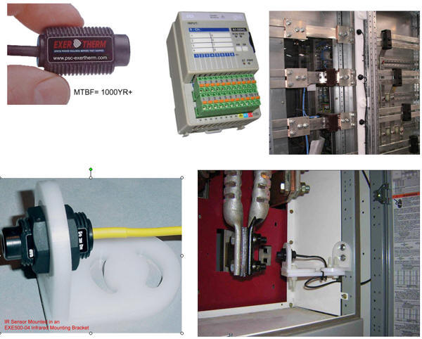
The next generation is here, 24 hours a day, 7 days a week, 365 days a year thermal monitoring. Using small Infrared (IR) sensors as well as other temperature sensors, each critical item can be monitored in real time. Such systems can use their own data loop, which provides for a nice back up to the standard BMS loop. As well as offering the choice to be integrated into the present BMS systems. Once installed, there’s no dependency on the settings of a camera or competency of a technician.
Protective panels do not need to be removed to check on a PDU or piece of switchgear if changes in loadings occurred due to bringing new loads online. Since the data is logged 24/7/365, the data can be reviewed for abnormal transients that would indicate abnormal events in heat or electrical loading of a system.
With the roll out of the blade servers the increased branch loading also reflects back to the switchgear. The effects of the added power requirements normally wouldn’t be noted till the next thermography cycle, and it may be too late by then. The same constant thermal monitoring system can be used to monitor and alarm the hot and cold server rack isles.
[an error occurred while processing this directive] These high-density blade servers aren’t less efficient power wise, they just occupy less space, so they emit more heat per cubic foot due to their density, compared to the old, larger server configurations. When “more” servers are installed into one rack, the result is an increase in the BTU’s generated (dissipated heat) from the same rack. As well as in increase in current draw from the branch circuit. So keeping an eye on these hot and cold isles becomes just as critical as the electrical components ( PDU’s, UPS’s, & Switchgear).
Continuous thermal monitoring in critical switchgear, while new to the USA, has been proven over the past 5 years via numerous successful installations in blue chip multinationals located in the UK, utilizing the patented IR technology. Since these small IR Sensors are non-conductive plastic, passive, (requiring no external power), and with unsurpassed MTBF, they can be placed INSIDE critical enclosures with out concern. Certain switchgear manufacturers in the US are already working to offer OEM installation of this system, which provide trend data, and independent alarms per sensor.
The “Data Acquisition Cards” to which the sensors are wired, can be mounted either in equipment cabinets or external to the switchgear. Each Card accepts 8 sensor inputs. There is a choice of Data Cards, those that communicate using an “ExerTherm” data loop, which work with the ExerTherm software to manage the system, (this can also provide alarm status flag to existing systems through the supplied dry contacts). Alternatively, cards that communicate directly to the likes of Modbus and other key protocols ( ie. Profibus), utilize existing bus cabling, and provide SCADA system compatibility. The system can also be web enabled via Ethernet connection enabling access from intranets, or even combined with the latest wireless data transfer technologies to provide continuous monitoring of critical equipment in remote locations. The system can easily be retrofitted during a suitable shutdown, installed during new construction, and be expanded as required in either case. The feature of Easy Expansion enables progressive installation in critical sites, which only have partial system shutdowns.
The available mounting systems provide for a flexible mounting option that’s comprised of all non-conductive high temperature material. Since the IR sensors are totally passive and require no bias voltage or current, they require no re-calibration. So they are truly a set and forget item.
In electrical equipment, connections, and components (all known as a target) it’s more important to know the temperature “rise” being experienced. The “temperature rise” is the effect of the losses within the “target”. For a connection, the losses are a result of the resistance in the connection. As discussed above, the higher the contact resistance, the higher the losses, so the greater the temperature rise.
Thus in thermal imaging, the accepted method of temperature measurement for electrical equipment is Delta T ( ∆T), i.e. the rise above ambient (surrounding air temp), of the target equipment being measured. The ExerTherm IR sensors employ exactly the same method.
Besides Data Centers
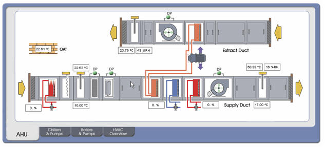
In as much as data centers were used as the primary example of where constant thermal monitoring is being used, ExerTherm has many more applications than just monitoring the electrical system, HVAC system, and temperature of a data center. Any facility or manufacturing plant that is focused on achieving greater uptime and getting the most from their scheduled maintenance can benefit.
Monitoring electrical distribution equipment for
manufacturing plants will not only maximize uptime, but also maximize safety and
minimize damage. Many of the large scale manufacturing plants use much more
power than a data center. This potential energy unleashed during a failure or
arc flash can damage not only the electrical distribution equipment, but also
very expensive robotic and manufacturing machinery and any personnel that may
have been in the area as well.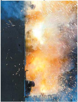
Within the manufacturing machinery there are also “bearings” of concern. In high cycle rate and or close tolerance machining, minor bearing wear can increase the rejection rate. Bearings starting to wear will exhibit an increase in their operational temperature. If left unnoticed, loss of critical tolerances will cause rejects, and eventually a catastrophic failure in the machine. This failure will lead to more expensive repair and an extended down time. The same can be said for motors, gearboxes and pumps as well, leading us into the most large scale manufacturing / processing plants as well as the shipping fleets.
A larger cruise line company has deployed ExerTherm on their modern vessels. These floating cities on the water not only generate and distribute the power for their small city, but for their electric propulsion. Loss, damage or even fire of electrical equipment or drive components is much more than just unscheduled down time; like data centers and large scale manufacturing, the consequence can be significant loss of profit + additional costs. Continuous thermal monitoring provides a solution which substantially mitigates that risk.
Conclusion
The power to monitor any component of electrical junction or device is now available. Not only to monitor it, but also to record its profile over time, which gives us information we have never had before. We can now know what occurred in the past, what’s happening today and predict what’s going to happen in the future. Finally giving us the power for true Predicative Maintenance in response to the never ending growth we see in front of us.
[an error occurred while processing this directive]
[Click Banner To Learn More]
[Home Page] [The Automator] [About] [Subscribe ] [Contact Us]